
Creating the library components
The first step is to collect the necessary information needed to create a cable head assembly:
- Connector Head data sheets.
- Crimp information and drawings.
- Cable data.
- Heatshrink data.
Additional tools may be required to assemble the cable, but that will be saved for a later discussion. For now, we have taken note on what is required to create the library parts for drawing the cable assembly. We will start by creating a multi-part component for each connector head. The first part in this multi-part schematic component will be the graphical diagram of the connector head, which provides the visual representation for the assembly drawing. Figure 1 shows an example of how this will be styled, and will be scaled 1:1 with the real physical part.
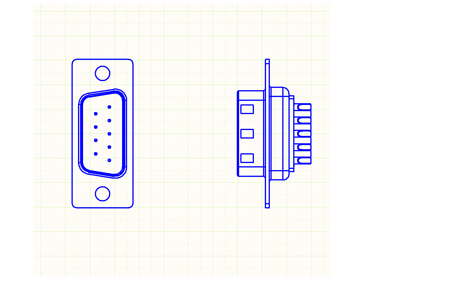
Figure 1. 1:1 drawing of the connector head
The second part in the multi-part schematic component, will be the traditional IEEE-315 style electrical schematic symbol for the multi-position connector (see Figure 2). This second part provides the electrical pins and diagram for generating a netlist of connections, so later on we can generate the necessary post-assembly test jigs and programs.
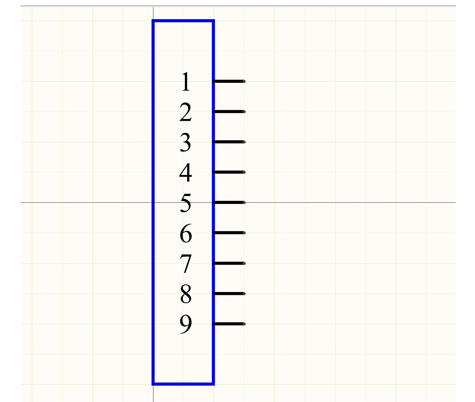
Figure 2. Schematic Symbol of Connector
The final part is what I call the line item bubble (refer to Figure 3). This bubble will be used to make notes on the drawing linking what the part is to its reference to the bill of materials (BoM).

Figure 3. Schematic Symbol of Line Item
These are coordinated into separate gates (or subparts) within a library component of the library editor. Each part has important information with regards to the cable assembly. That importance will be explained later on, but for now I will discuss how to create the connector head component and cable component.
The Connector Head Component:
2D Connector Head Drawings - Part A and C
The connector head part is an accurate scaled plan-view of the real connector. While you could draw this directly in the schematic library editor, most connector manufacturers provide drawings in DXF or DWG format for MCAD tools. So it will be faster to obtain such a drawing as seen in Figure 1, by first importing the DWG or DXF drawing of the connector head into the Schematic Editor. When performing this step, ensure that the scale is 1:1. You can also generate 2D front/top plan drawing in DXF from 3D mechanical models and then import those to Altium Designer. Once imported into the Schematic Editor, make sure you select the entire connector head and unionize the entire selection by going to Tools » Convert » Create Union from Selected Objects. Once that is done, you can then copy and paste the entire primitive drawing into the library editor as seen in this figure below in Figure 4:

Figure 4. Profile view of a DSUB connector within Altium’s Library Editor
In the sample library (link here)[a], you will see that part A is the face (front) view and part C is the profile (top) view. I created the library in this particular manner based on my previous work experience in creating cable components. However, it is ultimately up to the user or design group to decide which part of the component will be designated by face and profile. Whatever you choose, make it consistent across all your connector library parts.
The Line Item Bubble - Part B
The following parts within the component are designated as a schematic symbol and line item bubble. The line item bubble has a specific purpose. Its function is to designate the graphical representation and reference it to the BoM. To create the line item bubble, a simple Full Circle is placed in the center of the Schematic Library Editor, and within the component properties you add a parameter Line Item. The value of the parameter is then placed in the centre of the Full Circle. The result of the component drawing is shown in figure 5 below:

Figure 5. Line Item Bubble with parameter embedded
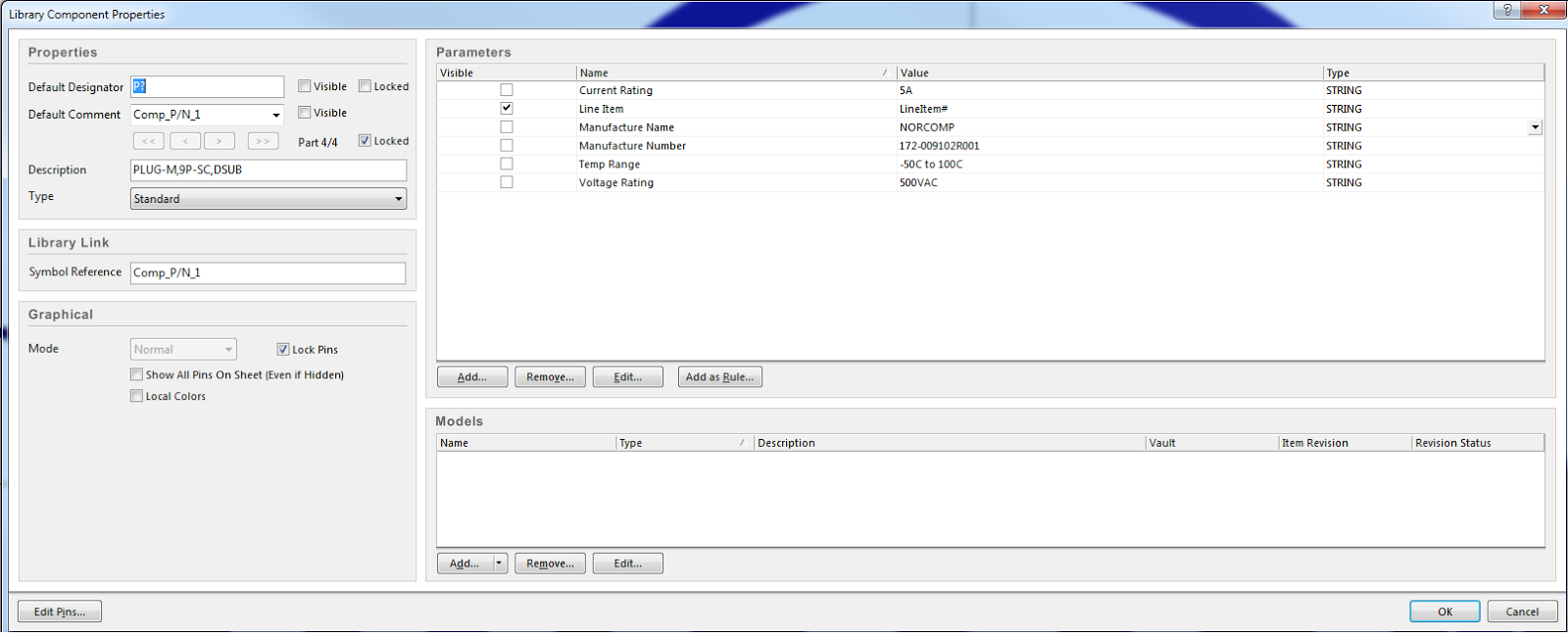
Figure 6. If you notice within the Component Properties, the Line Item is added and made visible
Line Item Parameter
Although the Line Item Parameter is shown in Figure 5, it is set to invisible once you’ve placed it in the Line Item Bubble. This done so that when you place the connector parts within the Schematic Editor for your cable drawing, this parameter’s text will not show up until you reached the last part of the component, which should be the Line Item Bubble. More information on this will be explained later when we discuss on how to actually begin drawing cable assemblies.
Now that we have covered the connector head component, the next component to create is the cable itself, which is much simpler to than the connector head.
Cable Component:
Why create a cable component?
First - maybe to state the obvious but it should be asked - why create a cable component? Doesn’t Altium Designer already have wire, bus and harness objects? Good question. Bare in mind though that these objects are for establishing connectivity (i.e. building a net list), and do not represent the physical cable you would have to purchase or manufacture. For cable assembly of course we need this information represented in the BoM for supply chain resolution.
The cable component will only encompass two sub-parts in it: One being the schematic symbol, and the other being the Line Item. Most cable drawings I’ve studied use the oval shape shown above. This provides an aesthetically pleasing look. The top and bottom are just arcs connected by dotted line objects. So, as followed, Figure 7 shows a diagram of the cable in schematic format:

Figure 7. Schematic Symbol of Cable Drawing
Pins in a cable?
Referring again to Figure 7, the dots that are distributed evenly in the middle of the drawing are pins with a unit length of 0 mil. These ‘pins’ represent the electrical connectivity of the cable itself, and will ultimately be linked in the netlist with connections to the connector heads. When you are wiring up the design, it then becomes a simple and quick process. However, this will be further elaborated a future installment.
Line Item for the Cable Component
The second module for the cable component is the line item bubble, much the same as the one used in the connector head component. After that, you have completed making the cable library component. The reason we have this component setup is that many users will draw out their cable assemblies in different sheet sizes (A, B, C, etc.), and the cable itself can be drawn by the designer different lengths or in more complex shapes (e.g. in a serpentine fashion). Therefore the line item sub-part offers the guarantee that you always have the right parameter text to represent the cable used, and it can be placed on the schematic sheet wherever needed.
In the next Cable Design blog, I will show how to create crimp and heatshrink components and demonstrate how all the components assemble together to generate an elementary cable drawing. Keep reading!
[a]Need to add HTML link to zip file for download